It’s been a while since I wrote my last post. Many many things happened both in my life as well as work. Not an excuse for my lack of posting, but I do plan to get back to blogging more consistently in the year 2023.
What do we have here today?
In today’s edition, I bring you I script I wrote to move T1 gateways across Edge Clusters in NSX-T. It can programmatically move hundreds of T1s in a couple minutes.
Why would I need to move my T1 Gateways across Edge Clusters?
There are multiple scenarios that would trigger the need to move / evacuate T1 gateways to a different Edge Cluster. The most common are:
During a NSX-V to NSX-T migration, Migration Coordinator will, by default, put all T1 gateways in the same Edge Cluster that is being used for the T0s. In an architecture where there is a dedicated Edge Cluster for T0 ECMP / Uplink, and Edge Cluster/s used for T1 Stateful services (such as load balancing) this is not ideal.
A 10-node XL Edge Cluster can only host up to 400 Small load balancers. Going over this limit will require to build an additional Edge Cluster. vRA can only deploy Load Balancers to a single Edge Cluster at any given time per any given Network Profile. If we reach the limit, we either create the new cluster and change the network profile to the new cluster, or, we can migrate the current T1s to the new cluster, and keep using the one we previously had in the network profile
Rebalancing of T1 Gateways across Edge Cluster for maintain a similar number of T1s across all edge clusters.
How do I use this script?
In the initial comments of the script there is an explanation of the usage
<################################################
Move (T1s) across edge clusters
Author: @ldelorenzi - Jan 23
Usage:
moveT1s.ps1 -nsxUrl <NSX Manager URL (with HTTPS)) -sourceClusterName <Edge Cluster Name> -destinationClusterName <Edge Cluster Name> -execute <$true/$false> -count <count of load balancers to move>
Credentials will be asked at the beginning of the run
################################################>
To dive a little bit deeper into these parameters:
nsxUrl: The NSX-T manager we will be hitting with this script. Including HTTPS
sourceClusterName: The name of the Edge Cluster that hosts the T1 Gateways we want to move
destinationClusterName: The name of the Edge Cluster that will receive the T1 Gateways from the source cluster
execute: By default, the execute flag is set to false. This means that if no value is used in the script, it will default to false. If execute is false, the script will only show us what T1s were found in the source cluster and therefore will be moved to the destination cluster
count: If you don’t want to fully evacuate the cluster and you want to just move some T1s from source cluster to destination cluster, you can set a value for the count parameter and that will limit the amount of T1s that are moved.
Interesting things about the Script
If you look at the code you will see that I built my own wrapper for invoke-RestMethod called restCall – this function has logging included as well as retries. If you’re going to have a lot of REST API calls in your scripts, it could make sense to include something like this!
The ‘movement’ of T1 Gateways actually involves patching the T1 SR object with its new cluster ID. The script finds the Edge Cluster IDs using the names provided at the beginning of the run. This makes it friendlier for users / admins since just the name can be used instead of having to find the id.
Closing Note
I hope you enjoy this post and make use of this script in your environments. If you liked this, please share it!
Hello Everyone! On today’s post, I’m going to do a step by step walkthrough of a SaltStack Config (from now on, SSC) enterprise install. The SSC enterprise install is meant to be used in production-grade environments, and can handle up to 5000 Salt Minions per master!
I will also cover how scale-out the deployment and add a new Salt Master (in a cluster configuration) to the deployment after it is finished.
In addition to this, I will cover how to configure a Git repo as a shared storage across masters.
Lastly, I will cover how to prepare a vRA Cloud Template to install the Salt Minion, configure it to use multiple masters, and run a Salt State on the deployment!
Let’s start! Buckle up!
Architecture
This deployment is going to have:
One VM for PostgreSQL and Redis – Required for persistent & in-memory database components. These two components could be also separated across two different VMs (and configured in HA, but only for manual failover).
One VM for RaaS (Responder as a Service) – This is going to be the GUI of SSC. The RaaS component can also be deployed in a cluster mode using an external load balancer, but I’m going to use a single one in this post.
Two VMs, one for each Salt Master, that will form a cluster. The secondary master and the cluster will be generated after the initial deployment.
Both Salt Masters will be configured to use a Github repository.
All VMs are running Centos 7 as the operating system.
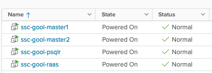
Architecture
This is what my servers look like, from a vSphere point of view.
VMs
List of Steps
What do you need to do to carry out this deployment?
The first list of steps is based on this LINK, which is the ‘Installing and Configuring Saltstack Config’ Official Documentation from VMware.
Prepare the template for the VMs (you can prepare each VM separately but there are common items across all VMs)
Deploy the 4 VMs (take note of the IP addresses)
Prepare the VM that will become the Primary Salt Master
Prepare the VMs that will only be Salt Minions (the PostgreSQL / Redis & the RaaS)
Download & Copy the SSC installer to the Primary Master
Copy and edit the top state files
Edit the SSC settings Pillar file
Apply the highstates to the nodes
Install the License Key
Install and configure the Master Plugin on the Primary Salt Master
Log in for the first time and change the default credentials
Accept the Primary Salt Master key
Optional: Configure Backup for files (if not using a complete backup solution), Set up custom SSL certificates, SSO. (won’t be doing this as a part of this post) -> Link1, Link2, Link3
At this point, you’re going to have a functional SSC enterprise install, but you will only have a single master node. You still need to configure the Secondary Master, the cluster, and the repository!
The second list of steps is based on multiple sources and testing, since there isn’t a single source of information to configure all of this. Which is why I’m attempting to write this and condense it! I will be adding links throughout the steps.
Prepare the VM that will become the Secondary Salt Master
Copy the SSC installer to the Secondary Master
Prepare all the other minions to use Primary and Secondary Salt Masters
Copy Primary master key to the Secondary Master
Edit the RaaS configuration file (master plugin) on the primary master to add the Cluster ID
Install and configure the Master Plugin in the Secondary Master
Edit the RaaS configuration file (master plugin) on the Secondary Master to add the Cluster ID
Start Salt-Master on the Secondary Master and accept the Secondary Salt Master key
Install GitPython on both Salt Masters
Configure the GitFS filesystem and Github repository
Configure a Cloud Template on vRA to install the Salt Minion and configure the two masters
Create a Job using the Salt State hosted in Github
Run the Job!
Don’t be scared! I will be explaining every single step so you’re also able to have a successful deployment. Let’s start!
1: Prepare the template for VMs
You need to install OpenSSL, EPEL, and two libraries for Python (cryptography and OpenSSL) so this is what you need to run:
Create a master.conffile in the /etc/salt/minion.ddirectory and add the following text to configure the minion to use itself as a Master.
master: localhost
Create a the minion_id file in the /etc/salt/ with a descriptive name for the minion using vi, in this scenario, for example, my Primary Master’s minion_id is ssc-gool-master1. This will be autogenerated based on hostname on the first run of the salt-minion service if its not set previously.
Create a master.conffile in the /etc/salt/minion.ddirectory and add the following text to configure the minion to use the Primary Salt Master as its Master
master: IP_OF_MASTER
Set the minion_id (located in /etc/salt) to a descriptive name using vi, in this scenario, for example, my RaaS minion_id is ssc-gool-raas.
Copy the installer to a folder within the Primary Master (it can be the root directory as well), for example, /ssc-installer, and assuming our file is called ssc_installer.tar.gz.
The top state files will be used by the orchestration to install the RaaS, Redis and PostgreSQL nodes.
At this point, you should take note of the Minion ID and the IP addresses of your three nodes, since you will be using them in the following steps. In my case, this is the information:
MINION ID: IP ADDRESS
ssc-gool-master1: 10.0.0.2
ssc-gool-psqlr: 10.0.0.3
ssc-gool-raas: 10.0.0.4
Now, you need to copy and edit the orchestration configuration files.
Important: The instructions below assume that this is a ‘greenfield’ Salt installation. If this is not the case, you might need to edit the following commands to work within your directory/folder structure.
Navigate into the sse-installerfolder (this is the folder that was extracted from the tar.gz file) and run the following commands:
In the /srv/pillar directory, you now have a file named top.sls. Edit this file to define the list of Minion IDs (not IP addresses) that you recorded previously. This is how it looks in my environment
Since as mentioned earlier, my 3 Minion IDs are ssc-gool-master1, ssc-gool-psqlr and ssc-gool-raas.
Also make sure that in the /srv/salt directory you also have a file named top.sls that looks like this:
base:

  {# Target SSE Servers, according to Pillar data #}
  # SSE PostgreSQL Server
  'I@sse_pg_server:{{ grains.id }}':
    - sse.eapi_database

  # SSE Redis Server
  'I@sse_redis_server:{{ grains.id }}':
    - sse.eapi_cache

  # SSE eAPI Servers
  'I@sse_eapi_servers:{{ grains.id }}':
    - sse.eapi_service

  # SSE Salt Masters
  'I@sse_salt_masters:{{ grains.id }}':
    - sse.eapi_plugin
7: Edit the SSC settings pillar file
You need to edit four different sections in the SSC settings pillar file to provide the values that are appropriate for the environment. These settings will be used by the configuration state files to deploy and manage your SSC deployment.
Navigate to the /srv/pillar/ssedirectory and edit the sse_settings.yamlfile.
Section #1: Change the values of the four variables to match your Minion IDs. In my case, this looks like this:
# Section 1: Define servers in the SSE deployment by minion id
servers:

  # PostgreSQL Server (Single value)
  pg_server: ssc-gool-psqlr

  # Redis Server (Single value)
  redis_server: ssc-gool-psqlr

  # SaltStack Enterprise Servers (List one or more)
  eapi_servers:
    - ssc-gool-raas

  # Salt Masters (List one or more)
  salt_masters:
    - ssc-gool-master1
Section #2: Edit thefollowing variables
pg_endpoint: use the IP address (or DNS name) of the PostgreSQL server. In my environment, this is 10.0.0.3.
pg_port: Port for PostgreSQL. In my environment, I left the default values
pg_usernameand pg_password: Credentials for the user that RaaS will use to authenticate to PostgreSQL
This section looks like this:
# Section 2: Define PostgreSQL settings
pg:

  # Set the PostgreSQL endpoint and port
  # (defines how SaltStack Enterprise services will connect to PostgreSQL)
  pg_endpoint: 10.0.0.3
  pg_port: 5432

  # Set the PostgreSQL Username and Password for SSE
  pg_username: salteapi
  pg_password: VMware1
Section #3: Repeat the previous steps but this time, to match your Redis parameters. Since we’re using the same server for both PostgreSQL and Redis, the IP will be the same.
# Section 3: Define Redis settings
redis:

  # Set the Redis endpoint and port
  # (defines how SaltStack Enterprise services will connect to Redis)
  redis_endpoint: 10.0.0.3
  redis_port: 6379

  # Set the Redis Username and Password for SSE
  redis_username: saltredis
  redis_password: VMware1
Section #4: Edit the variables that are related to the RaaS node
Since this is a fresh installation, do not change the eapi_usernameand eapi_passwordvalues. You will change the default password at a later step
eapi_endpoint: set it to match the IP address of your RaaS node. In my environment, this is 10.0.0.4
eapi_ssl_enabled: default is set to true. SSL validation is not required by the installer but it will be likely a security requirement in environments that use CA certificates.
eapi_ssl_validation: default is set to false. This means that the installer will not validate the SSL certificate.
eapi_standalone: default is set to false. This variable would be true in the case of the LCM install, in which all components are shared in a single node.
eapi_failover_master: default is set to false. This would be used if you were to configure a Multi Master configuration in failover mode (not active-active) and from within the installer. This will keep its default value since the scaling out will be done afterwards.
cluster_id: This variable defines the ID for a set of Salt masters when configured in a multi-master configuration. The default value should be left here, this will be edited at a later step, once the deployment is already running.
This is what my file looks like:
# Section 4: eAPI Server settings
eapi:

  # Set the credentials for the SaltStack Enterprise service
  # - The default for the username is "root"
  #   and the default for the password is "salt"
  # - You will want to change this after a successful deployment
  eapi_username: root
  eapi_password: salt

  # Set the endpoint for the SaltStack Enterprise service
  eapi_endpoint: 10.0.0.4

  # Set if SaltStack Enterprise will use SSL encrypted communicaiton (HTTPS)
  eapi_ssl_enabled: True

  # Set if SaltStack Enterprise will use SSL validation (verified certificate)
  eapi_ssl_validation: False

  # Set if SaltStack Enterprise (PostgreSQL, eAPI Servers, and Salt Masters)
  # will all be deployed on a single "standalone" host
  eapi_standalone: False

  # Set if SaltStack Enterprise will regard multiple masters as "active" or "failover"
  # - No impact to a single master configuration
  # - "active" (set below as False) means that all minions connect to each master (recommended)
  # - "failover" (set below as True) means that each minion connects to one master at a time
  eapi_failover_master: False
There is also a Section #5, but none of the values need to be edited at this step. These are the customer_idvariable, which is a variable that uniquely identifies a SSC deployment, and the cluster_idvariable, which will be edited once the deployment is already running and the scale-out is done.
8: Apply the highstates to the nodes
At this point, it would be wise to take snapshots of all your nodes, in case something goes wrong with applying the highstates, instead of having to troubleshoot a failed installation, it might be easier to rollback to the snapshot state and start over from this point.
Having said that, to apply the highstates, you need to do the following:
Accept the keys on your Primary Master, you can do that by running the command sudo salt-key -A which will accept all unaccepted keys (at this point, 3)
On your Salt Master, sync your grains to confirm that the Salt Master has the grain data needed for each minion. Since this is a fresh install, you can just run the command to target all the minions, which at this point are just 3.
sudo salt \* saltutil.refresh_grains
Then, run the following command to refresh the pillar data on all the minions
sudo salt \* saltutil.refresh_pillar
Lastly, run the following command to confirm the return data for your pillar is correct
sudo salt \* pillar.items
Confirm that the minions have received the pillar data that you edited on the sse_settings.yaml file, such as IP addresses, Minion IDs, etc
Now that you confirmed the data, it is time to apply the highstates to each node, by running the following command: sudo salt MINION_ID state.highstate – The PostgreSQL database should always be applied first
Which in my environment would look like:
sudo salt ssc-gool-psqlr state.highstate
sudo salt ssc-gool-raas state.highstate
sudo salt ssc-gool-master1 state.highstate
Confirm that the result of applying the highstates is succesful.
Note: you might get a ‘Authentication Error Occurred’ when applying the highstate to the Salt Master. This is expected, and it is deplayed because the Salt Master has not authenticated to the RaaS node yet. This will be solved at a later step.
If this has been successful, you now have a functioning install of SSC. But you still need steps to complete, let’s continue!
9: Install the License Key
To install the License key
Get your License Key from My VMware / Customer Connect (a vRA license is used)
Create a file with a filename ending in _licensesuch as ssc_licensefor example
Edit the file and add your license key number.
Change ownership of the license file and copy the file to the /etc/raasdirectory
Restart the RaaS service: sudo systemctl restart raas
10: Install and configure the Salt Master Plugin
The Salt Master plugin allows the Salt Masters to communicate with SSC. The master plugin is installed on every Salt Master in your environment that communicates with SSC. At this step, you will only install it on the primary Salt Master
Log in to your Salt Master
The master plugin is located in the sse-installer/salt/sse/eapi_plugin/filesdirectory. cd into that directory.
Install the Master Plugin by manually installing the Python wheel, using the following command, and replacing the exact name of the wheel file.
Note: I had to do this step while being logged in as the root user since I was not able to generate the file even with a sudoer user. If this is your case, just switching to the root user and running the command will do the trick.
Edit the generated raas.conffile and update it to use your RaaS server
sseapi_server: Since you enabled SSL at a previous step, the URL should be https://IP_ADDRESS_OF_RAAS – in my environment, it would be 10.0.0.4
sseapi_ssl_validate_cert: However, since you’re not using a CA-signed cert, you should disable the validation to allow for the communication between the Master Plugin and RaaS
This file has more parameters that can be edited at this stage, for example, to set a custom certificate, or specific performance configurations. For more information, visit: LINK
Restart the Master Service: sudo systemctl restart salt-master
You can also check and edit the RaaS configuration file to edit RaaS related parameters. I won’t be covering them in this post and will be using the default values, but more information can be found at: LINK
11: Log in and change the default credentials
Log in to the SSC interface with the default credentials
Then go to Administration -> Authentication -> Local Users, and change the password for the root user
12: Accept the Salt Master Key
Go to Administration -> Master keys. You will see your Master node with a Key in the ‘pending’ state. Accept it.
At this point, you should see your minions pop up in the ‘Minions’ screen.
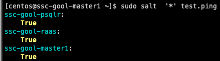
You can then run a simple command, such as test.ping to make sure that you can connect to your minions. For example:
Testing ping command from salt.master
You can also test this from the RaaS console, by selecting the minions and running the same job
Running test.ping job from the console
Congrats, if you made it here, you have a functioning distributed install of SSC! Now you will scale this out to allow for multiple masters and a shared repository!
A little break
At this point, we have configured our initial deployment. From now on, I will cover how to scale this out to add a secondary master, and configure a git repository!
14: Prepare the VM that will become the Secondary Salt Master
Follow Step #3 from the list, but this time using the Secondary Master VM!
15: Copy the SSC installer to the Secondary Master
Follow Step #5 from the list, but only copy the file, since you already downloaded it in that step.
16: Prepare all minions to use both masters
At this step, you need to edit the /etc/salt/minion.din all the minions to use both masters. In the case of the nodes that are masters, you can just keep the localhost value and add the value of the secondary master to each node. In the case of the nodes that are minions (PostgreSQL/Redis, RaaS) you can append the IP of the secondary master to the file. Keep in mind that this will now become a list, and the syntax changes. The files should look like this (using the IPs from my environment)
Restart the Salt Minion service on each node after editing the files: sudo systemctl restart salt-minion
17: Copy the Primary Master Key to the secondary master node
This is a requirement to be able to use a redundant master (regardless of it being configured in an active-active configuration or active-passive). The masters need to share the private and public key.
You should log in to the Primary Master and run the following commands to copy the files. This can be done with the root user if you run into any issue with accessing the folder. Overwrite the existing files if prompted.
cd /etc/salt/pki/master
scp master.pem USERNAME@IP_OF_SECONDARY_MASTER:/etc/salt/pki/master/
scp master.pub USERNAME@IP_OF_SECONDARY_MASTER:/etc/salt/pki/master/
Then, log in to the Secondary Master and restart the Master Service: sudo systemctl restart salt-master
18: Edit the RaaS configuration file (Master Plugin) on the primary master to add the Cluster ID
Since we’re going to place both masters in the same cluster, we need to make RaaS aware of this. This configuration is handled in the Master Plugin configuration.
To do this change, open the /etc/salt/master.d/raas.conffile on the Primary Master and edit the value of the sseapi_cluster_idvariable. In my environment, this looks like this:
sseapi_cluster_id: goolcluster # SSE cluster ID for this master (optional)
As we saw on the Architecture image, my cluster will be called goolcluster
Then, restart the Salt Master service on the Primary Master: sudo systemctl restart salt-master
19: Install and configure the Master Plugin in the Secondary Master
Follow Step #10 using the Secondary Master VM.
20: Edit the RaaS configuration file (Master Plugin) on the secondary master to add the Cluster ID
Follow Step #18 using the Secondary Master. Make sure to use the same Cluster ID, in this case, goolcluster.
21: Start Salt-Master on the secondary master and accept the second Salt Master Key
Log in to the Secondary Master, then run the following command to start the Salt Master service: sudo systemctl start salt-master
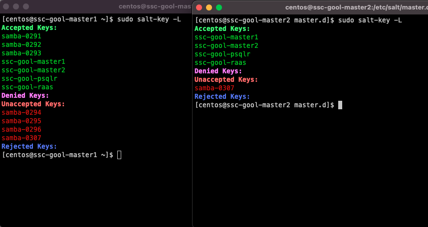
Then, log in to SSC using a browser, and accept the Master Key for the secondary master. Once it is accepted, it should look like this:
Both master keys accepted
At this point, since all minions are configured to use both masters, you will get pending minion keys in the SSC console. You can accept them there.
Note: Since both masters are part of the same cluster, SSC will recognize them as the same node. They will show up in the ‘Pending’view of keys, but they will show up as already accepted. You need to accept them again (since this will be accepting the key in the secondary master). In the future, new minions will only need to be accepted once, since accepting on SSC will run the job to accept keys on both Salt Masters
The next steps will be about configuring the GitFS filesystem, which is one of the ways you can use a shared filesystem for both masters. It is a requirement to have a shared filesystem across masters, otherwise you could have inconsistent information depending on what master is being used for any given Job instance.
22: Install GitPython on both Salt Masters
Configuring a GitFS filesystem in a Salt Master can be accomplished through two methods:
Via GitPython
Via pygit2
I was having trouble with pygit2 in CentOS and getting Salt to recognize the version (this has been reported in multiple Git and Stackoverflow posts), so I ended up using GitPython instead, and this is what I will be describing.
To install GitPython, and its dependencies (such as the git cli), log in to both Salt Masters and run the following command: sudo pip3 install GitPython
After installing it, make sure that it shows up as being used by Salt. Salt uses its own Python version so some packages don’t always get recognized.
Run the following command: salt -V
[centos@ssc-gool-master2 ~]$ salt -V
Salt Version:
          Salt: 3004.1

Dependency Versions:
          cffi: 1.9.1
      cherrypy: Not Installed
      dateutil: Not Installed
     docker-py: Not Installed
         gitdb: 4.0.9
     gitpython: 3.1.20
        Jinja2: 2.11.1
       libgit2: Not Installed
      M2Crypto: 0.35.2
          Mako: Not Installed
       msgpack: 0.6.2
  msgpack-pure: Not Installed
  mysql-python: Not Installed
     pycparser: 2.14
      pycrypto: Not Installed
  pycryptodome: 3.14.1
        pygit2: Not Installed
        Python: 3.6.8 (default, Nov 16 2020, 16:55:22)
  python-gnupg: Not Installed
        PyYAML: 3.13
         PyZMQ: 17.0.0
         smmap: 5.0.0
       timelib: Not Installed
       Tornado: 4.5.3
           ZMQ: 4.1.4

Salt Extensions:
        SSEAPE: 8.6.2.11
You can see that GitPython shows up as installed and with version 3.1.20, while pygit2 is not installed.
23: Configure the GitFS filesystem and Github Repository
The URL for the repository that I’m using now is public, and it is https://github.com/luchodelorenzi/saltstack -> you can use it as well for doing the same tests I will be doing on this deployment.
All the steps of this configuration need to be done on both Salt Masters, since they’re now running in a cluster
Edit the fileserver_backend parameter and add the ‘gitfs’ filesystem to the /etc/salt/master.d/raas.conffile.
Create a new file in the same directory, called gitfs.confand add the following parameters
gitfs_provider: gitpython

gitfs_update_interval: 60

gitfs_base: main

gitfs_remotes:
 - https://github.com/luchodelorenzi/saltstack.git
Note: the same raas.conf file could have been used to append the gitfs parameters. However, Salt will look for all *.conf files in the master.ddirectory, so separating this in a different file could make it easier to maintain / check.
What do each of the parameters mean?
gitfs_provider: The provider that will be used to leverage GitFS. In this case, GitPython
gitfs_update_interval: Update interval for gitfs remotes.
gitfs_base: Defines what branch or tag is used as the base environment. The main branch on my repository is main, but it can change depending on yours
gitfs_remotes: List of the repositories. Only adding one in this deployment. You can have multiple deployments, and some parameters are overridable per remote.
There are multiple other parameters for GitFS. For more information please follow this LINK on the GitFS section. You can also follow this other LINK for a GitFS walkthrough.
After configuring this, restart the Salt Master on both nodes, by running the following command: sudo systemctl restart salt-master
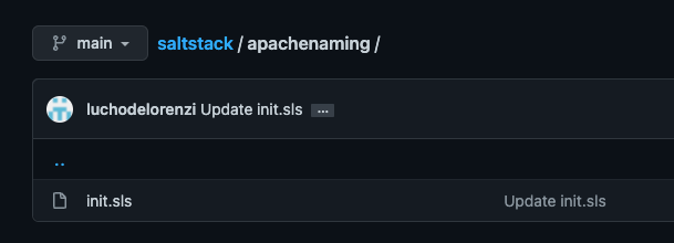
Now, you need to check if our files are being read from Github! Since the mapping was done to the base environment, running the following command will show every state file in that environment. For example:
The apachenaming state resides on Github, as you can see here:
Github Repository
So hooray, we can now use this Salt state from Github, and this is shared across both masters, has version control, you can use multiple repos, multiple branches. Pretty cool, isn’t it?
24: Configure a Cloud Template to Install the Salt Minion and Configure Two Masters
Since the vRA integration with SSC does not allow to integrate with Multiple Masters, I will use CloudConfig to perform the initial installation and configuration. As a prerequisite for this, your template should be prepared to use CloudConfig
This is the CloudConfig Code in the Template I’m using:
Run it to install the Salt Minion and point it to one of the masters
Change ownership of the minion.ddirectory to the ubuntu user which is the user that’s being used by CloudConfig in this template
Remove the 99-master-address.confthat was generated during the Salt Minion install
Create a new file with the addresses of the two Salt Masters (and using the correct list syntax)
Restart the salt-minionservice
After doing this, if I do a deployment, the minion will show up in both masters with a Pending state. Let’s go ahead and deploy a server!
This is the result of the deployment
If I go to the SSC console, I will see this Minion pop up under the pending keys
And you can see that this will come up as pending on both masters! This means that the changes on the master.conffile on this instance of the deployment worked.
samba-0307 is pending on both masters
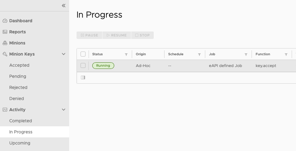
Now, if you accept the key on the SSC console, it will be accepted on both nodes. Accepting the key triggers a job that you can see on the Activity view.
Once the action is completed, the key will be accepted on both Masters, so both Masters wil be able to interact with the minion. This is a brief excerpt from the output of the job run
You can see that the action was executed on both masters, since they’re both part of a cluster.
25: Create a Job using the Salt State hosted in Github
The second to last step of this post. You will now create a job and use the Salt State located in the Github Repository.
Go to Config -> Jobs and click on Create Job
Under Command, select salt
Do not select any targets
Under Function select state.apply
Do not select an environment
Under states type in the name of the state, which is the name of the folder in Github. In this case, it will be apachenaming
Click on Save
Note: The SSC console does not have access to the GitFS filesystem, therefore, a State that exists in Github will never show up in the drop down list of States when the Job is being created. This is expected behavior, and why wou need to type the Salt state name.
26: Run the Job!
You made it! This is the last step! You will now test that you can actually run a job with a State file hosted on Git!
Go to ‘Minions’, select the minion that was deployed, click on Run Job and select the apachenaming job, and then click on ‘Run Now’
This job will install Apache on the server, and then configure the welcome page to show my name (LuchoDelorenzi) on it! This is the code of the state file (this is public on Github)
And after the Job is completed, this is the result!
FINISHED!
If you made it this far, congratulations! I know this has been a really long post full with information, but I hope that you found it simple enough to consume and be able to attempt this deployment (and tweak things for your environment) based on this post!
Closing Note
As usual, looking forward to feedback in the comments. And if you liked the post, please share it! The more people I can help, the better!
On today’s post, we will dive into a practical example to use vRealize Orchestrator Configuration Elements to help with a business need for vRA 8 Custom Forms!
The Problem
Customer X is using a single cloud template with multiple inputs backed by vRO Actions. The main input, and what defines pretty much all the rest, is the project selected. Given the complexity of the inputs, the cloud template can be used by all projects and by many different use cases.
Customer X was trying to improve the form loading times, which were around 10 seconds for the initial loading, plus 10 more seconds every time they changed the project in the form. This heavily impacted the user experience since it was giving a sensation of ‘slowness’ overall to anyone that was requesting the items.
The project defines, for example (there are more fields, but these are the ones we will use as example):
Hostname prefixes
Puppet roles
AD OUs
Portgroups
vCenter Folders
Each project has a ‘Project Map’ which contains different modifiers to then perform a different search in an external API, which has a cache of the objects needed, to reduce the time needed to gather the data (for example, sending API calls to vCenter to get folders)
However, the fact that the Project Map does not have all the information and needs to be processed in real time ends up adding more loading time to the form than desired.
A solution: vRO Configuration Elements
Emphasis on ‘A solution’ and not ‘THE solution’ since there could be other (even better!) ways to solve this problem, but this is how I approached it and will show it in this blog post.
vRO configuration elements, are originally used for example, for sets of variables that will be used in multiple internal actions/workflows, to avoid having the same data in many places, and for ease of managing. The configuration elements can be referenced in workflows or actions and the information is only changed in a single place.
However, there is another use we can give to configuration elements and that is using them as a Database!
All the configuration elements reside in the vRO DB, and the elements used can be of any of the types that exist within vRO.
Creating a Configuration Elements category called ‘Projects’
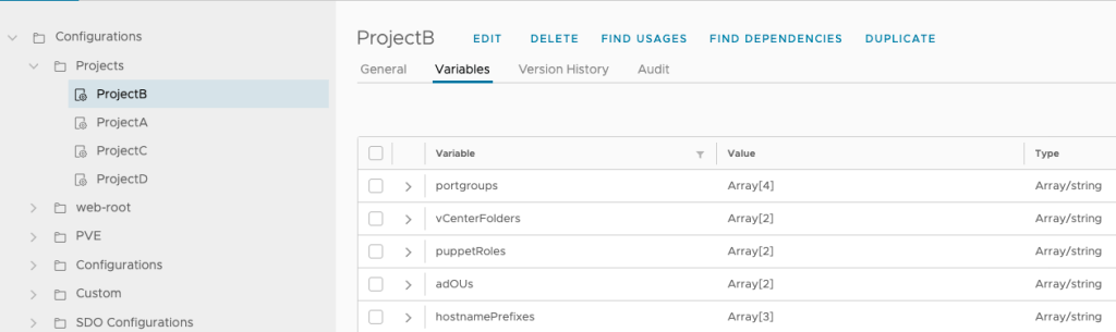
Create one configuration element per project, within that category. The easiest way to accomplish this is to create one configuration element, define all the needed attributes, and then just duplicate that configuration element to match all the projects you need – In this case, since we need to retun this to vRA Custom Forms, mostly in drop-down form, we will be using string arrays
One configuration element per project, with the variables mentioned
An action that will return the values to the custom forms, using two inputs, the Project we want to get the information from, and the value that we want to get. That makes the action reusable by multiple fields in the form: In this case, I called it getConfigurationElementValue and it can be seen on the following link: https://github.com/luchodelorenzi/scripts/blob/master/getConfigurationElementValue.js
An action or workflow that will:
Get the data from the external API
Populate the configuration elements with that data
This action/workflow can be scheduled to run every minute, every 5 minutes, depending on the need.
The data will be persisted in the vRO DB so that’s why I’m calling this a ‘database’ instead of a cache, however, it could very well be called a ‘persistent cache’ since all it is doing is to make the data available to the user as fast as possible but not doing any processing.
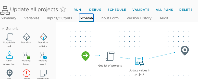
This workflow runs every 5 minutes and updates the values on all the existing projects (Configuration Elements)
The important thing to note here is that there isn’t any processing from the Custom Form to the vRO configuration elements when the user requests a catalog item!. Getting the data directly from the vRO DB without any processing at request time is what is going to give us the fastest loading times. All the processing is done in the background, without none of the requesters noticing!
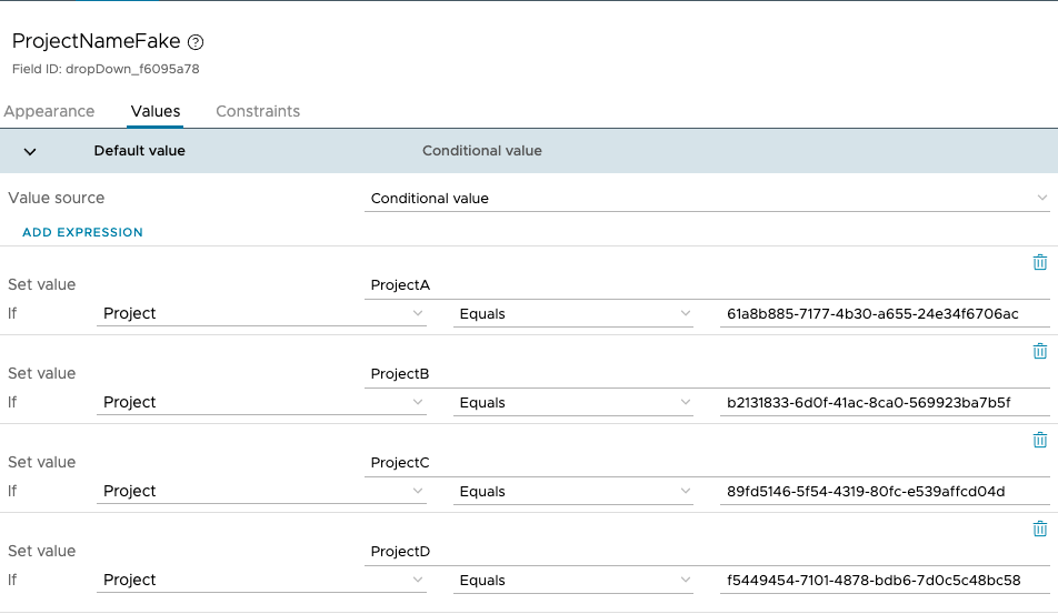
The last step is to refer to the getConfigurationElementValue action in our custom form
A small caveat – the way vRA 8 and the ‘Project’ field works is that even though the project shows the user the names to be chosen, it is actually processing the IDs, so in this case I added a hidden field called ProjectName which is what I will be actually using to convert the IDs to names (since the configuration elements are based on the name)
Mapping the Project IDs to namesUsing the getConfigurationElementValue action to get the values needed in the form
This is a small demo of how this works, take a look at the loading times for the form and changing the project! (And this is on a nested lab!)
Video Demo
Summary
To reiterate, the important things are:
No (or as little processing as possible if there is a field that cannot be used with configuration elements) should be done in the actions that are returning the data to the custom form
All the data should be processed in the background – The requester won’t be aware of it
Adding new projects it is as simple as duplicating one of the existing ones and changing the name. The way the workflows and actions are coded in this example will always look for every project (configuration element) below the ‘Projects’ folder
Getting the data out of the vRO DB directly via configuration elements instead of going to external sources, is the fastest way to get the values in the form.
Closing Note
I hope you found this interesting! It is using configuration elements in a way that might not be the most common usage, but it can bring great benefits to user experience when interacting with vRA requests. Having the data processed in the background and having really short form loading times will give the sensation of having more ‘speed’ to the tool itself!
Feel free to share this or leave a comment if you thought it was interesting!
On today’s post, as a continuation of the previous post (in which we talk about the VCF MGMT Domain) I will show a step by step guide of how to do a complete deployment of a VCF Workload Domain, subject to some specific constraints based on a project I was working on, using VCF’s API!
What’s this non-standard architecture like?
In this specific environment, I had to play around the following constraints
4 hosts with 256GB of RAM using vSAN, check the previous post for information about the MGMT domain!
3 Hosts with 256GB of RAM, using vSAN
3 Hosts with 1.5TB of RAM, using FC SAN storage
Hosts using 4×10 NICs
NIC Numbering not being consistent (some hosts had 0,1,2,3 – other hosts had 4,5,6,7 – even though this can be changed editing files on the ESXi, it is still a constraint and can be worked around using the API)
With this information, the decision was to:
Separate the Workload Domain into 2 clusters, one for NSX-T Edges and the other one for Compute workloads, given the discrepancies in RAM and storage configuration, they could never be part of the same logical cluster.
This looks something like…
It is impossible to deploy this using the GUI, due to the following:
Can’t utilize 4 Physical NICs for a Workload Domain
Can’t change NIC numbering or NIC to DVS uplink mapping
So we have to do this deployment using the API! Let’s go!
Once we have the token, we can use it in other API calls until it expires and we just either refresh it or create a new one. All the VCF API calls that are generated to SDDC manager (not internal API calls) will require the usage of a bearer token.
List of steps to create a workload domain
Commission all hosts from SDDC manager and create network profiles appropriately to match the external storage selection – In this scenario, we will have a network profile for the vSAN based hosts, as well as another network profile for the FC SAN based hosts. Hosts can also be commissioned via API calls (3.65 in the API reference) instead of doing it via the GUI, but the constraints I had did not prevent me from doing it via GUI.
Get all the IDs for the commisioned hosts – The API Call is “2.7.2 Get the Hosts” and it is a GET call to https://sddc_manager_url/v1/hosts using Bearer Token authentication
Create the Workload Domain with a single cluster (Compute) – The API Call is “2.9.1 Create a Domain”
Add the Secondary Cluster (Edge) to the newly-created workload domain – The API Call is “2.10.1 Create a Cluster”
Create the NSX-T Edge Cluster on top of the Edge Cluster – The API Call is “2.37.3 – Create Edge Cluster”
For each of these tasks, we should first validate our JSON body before executing the API call. We will discuss this further.
You might ask, why don’t you create a Workload Domain with two clusters instead of first creating the Workload Domain with a single cluster and then adding the second one?
This is something I hit during the implementation – If we check the Clusters object on the API, we can see it is an array, so it should be able to work with multiple cluster values.
"computeSpec": { "clusterSpecs": [
The info on the API call also points to the fact that we should be able to create multiple clusters on the “Create Domain” call.
Even worse, the validation API will validate an API call with multiple clusters
However, I came to learn (after trying multiples times and contacting the VCF Engineering team, that this is not the case)
For example, if our body looked something like this (with two clusters), the validation API will work!
However, when we go ahead and try to create it, it will fail, and we will see the following error on the logs.
ERROR [vcf_dm,02a04e83325703b0,7dc4] [c.v.v.v.c.v1.DomainController,http-nio-127.0.0.1-7200-exec-6]  Failed to create domain
com.vmware.evo.sddc.common.services.error.SddcManagerServicesIsException: Found multiple clusters for add vi domain.
        at com.vmware.evo.sddc.common.services.adapters.workflow.options.WorkflowOptionsAdapterImpl.getWorkflowOptionsForAddDomainWithNsxt(WorkflowOptionsAdapterImpl.java:1222)
So, as mentioned earlier, we need to first create our domain (with a single cluster), and then add the 2nd cluster!
1: Create a Workload Domain with a Single Cluster
We will first create our Workload Domain with the compute cluster, which in this scenario, uses external storage, and will use the secondary distributed switch for overlay traffic.
This is my API call body based on the API reference, to create a Workload Domain with a single cluster of 3 hosts, using two VDS, 4 physical NICs numbered from 0 to 3 and external FC storage, using the host IDs that I got after the previous step.
The DVS that is going to be used for overlay traffic must have the isUsedByNsxt flag set to true. In the case of a 4 NIC and 2 VDS deployment such as this one, it shouldn’t have any of the management, vMotion or vSAN traffic.
With the body, to execute the VALIDATE and EXECUTE api calls, we will do the following: (high level overview since we can use any REST API tool such as Postman, curl, invoke-restmethod, or any wrapper from any language that can execute REST calls)
The list of steps will be the same for all the POST API calls, changing the URL to match each specific call.
We should continue editing and retrying in case of errors until we get the validation to pass, do not attempt to execute the API call without validating it first!
The deployment will start and after a couple minutes we will see in the SDDC console that it was successful.
If it were to fail for whatever reason, we can troubleshoot the deployment by checking where it failed on the SDDC console as well as checking logs, but as long as the validation passes, it should not be a problem with the body we’re sending.
2: Adding a 2nd Cluster to the existing workload domain
To add a cluster to an existing domain, the first thing we need is to get the ID of the domain, that can easily be done with a GET call to https://sddc_manager_url/v1/domainsand selecting the ID of the workload domain we just created.
Once we get the ID, this is the body (following the API reference) to add a new cluster to an existing domain.
Even though we don’t need the cluster to be prepared for NSX-T (since it will only be used for Edges) setting the isUsedByNSXT flag to true will make the secondary VDS used by the uplink portgroups once we create a T0, which is what we want in this scenario – otherwise, we would not be using the 3rd and 4th NICs at all.
As discussed earlier, we should first run the POST call to validate in this case, the URL is https://sddc_manager_fqdn/v1/clusters/validations and after the body is validated, proceed with the creation removing validation from the URL
Last but not least, we need to create our NSX-T Edge Cluster on top of the 2nd cluster on the domain!
3: Create NSX-T Edge Cluster
The last piece of the puzzle is creating the NSX-T Edge Cluster, to allow for this workload domain to leverage overlay networks and communicate to the physical world.
To create the NSX-T Edge Cluster, we first need to get the Cluster ID of the cluster we just created (how many times can you say cluster in the same sentence?)
Now that we have the ID, this is the body to create two Edge Nodes, configure management, TEP and uplink interfaces, configure a T0 and a T1 instance, as well as configuring BGP peering on the T0 instance!
As mentioned before, please run the VALIDATE call first, in this scenario, a POST call to https://sddc_manager_fqdn/v1/edge-clusters/validations – after validation is passed, proceed to execute the call without the validations on the URL.
After this procedure is finished, we will have our workload domain with two clusters as well as a T0 gateway completely configured and ready to go! Simple and quick, isn’t it?
Closing Note
Leveraging APIs for VCF can help us not only to work with architectures or designs that are not able to be implemented due to GUI restrictions, but also greatly speed up the time we take in doing so!
I hope you enjoyed this post, and if you have any concerns, or want to share your experience deploying VCF via API calls, feel free to do so!